- 您现在的位置:买卖IC网 > Sheet目录337 > LDS8865002-T2-250 (IXYS)IC LED DVR WHT/CLR BCKLGT 16WQFN
LDS8865
If the device detects a sufficient input voltage is
present to drive all LED currents in 1x mode, it will
change automatically back to 1x mode. This only
applies for changing back to the 1x mode. The
difference between the input voltage when exiting 1x
mode and returning to 1x mode is called the 1x mode
transition hysteresis (about 600 mV).
Operation of PWM-based LED Current Control
The maximum current value in each of the
LDS8865’s three LED banks is factory preset; to set
each ILED below this value, a PWM (a duty cycle
based) control signal can be applied at the
PWM1/PWM2 pins.
Using a PWM control technique guarantees stable
WLED color temperature over a wide range of LED
currents. The LED color temperature set at the
factory preset maximum LED current does not vary
with respect to the average LED current unlike
conventional 1-wire LED current control methods.
The LDS8865’s PWM logic control circuits have been
designed to operate from 100 Hz to 100 kHz with
duty cycles higher than (0.02*F)% and lower than
(100 – 0.02*F)%, where F is the PWM control
frequency in kHz. The brightness dynamic dimming
range at 200 Hz is 25,000 : 1. PW M control
frequencies lower than 100 Hz are not recommended
(especially with short duty cycles) because LED
flicker may become visible.
When PWM current control is enabled, the LED
current is modulated from zero to 100% over a single
PWM period. For example, when PWM1/PWM2 is
logic high, the LED current is set equal to the
maximum factory preset value. When PWM1/PWM2
is logic low, the LED current is zero. The average
LED current level is then determined by the PWM
duty cycle that may be adjusted as described above.
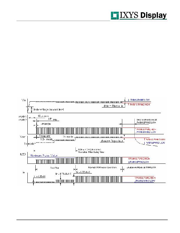
Figure 3 LDS8865 Timing Diagram
Note:
1. Timing diagram represents condition when LED forward voltage Vf is higher than Charge Pump Mode times(1.5) input voltage minus voltage
drop on current regulator VPCR and minus voltage drop on charge pump output resistance Rcp at Iled current through N LEDs.
Vf > CPM X Vin – Vd – Rcp x Iled x N; PWM duty Cycle = T PWM ON / (T PWM ON + T PWM OFF )
2. Timing Diagram is not to scale
? 2009 IXYS Corp.
Characteristics subject to change without notice
7
Doc. No. 8865DS, Rev. N2.1
发布紧急采购,3分钟左右您将得到回复。
相关PDF资料
LDS8866002-T2-300
IC LED DVR WHT/CLR BCKLGT 16WQFN
LDS8868-002-T2
IC LED DVR WHT/CLR BCKLGT 16WQFN
LDS8869-002-T2
IC LED DVR WHT/CLR BCKLGT 16WQFN
LDV100-012SN
POWER SUPPLY LED 90W 12V COMPACT
LDV100-024SN
POWER SUPPLY LED 100W 24V COMPAC
LE25S40MB-AH
IC MEM 4MBIT SERIAL FLASH 8SOP
LE25U20AMB-AH
IC MEM 2MBIT SERIAL FLASH 8SOP
LFDAS12XSIT
HARDWARE MC9S12XS 112-PIN
相关代理商/技术参数
LDS8866002-T2-300
功能描述:IC LED DVR WHT/CLR BCKLGT 16WQFN RoHS:是 类别:集成电路 (IC) >> PMIC - LED 驱动器 系列:PowerLite™ 标准包装:60 系列:- 恒定电流:- 恒定电压:- 拓扑:线性(LDO),PWM,升压(升压) 输出数:8 内部驱动器:是 类型 - 主要:背光 类型 - 次要:RGB,白色 LED 频率:500kHz ~ 1.5MHz 电源电压:4.75 V ~ 26 V 输出电压:45V 安装类型:* 封装/外壳:* 供应商设备封装:* 包装:* 工作温度:-40°C ~ 85°C
LDS8868-002-T2
功能描述:LED照明驱动器 6-Chan Chge Pump Bsd LED Driver
RoHS:否 制造商:STMicroelectronics 输入电压:11.5 V to 23 V 工作频率: 最大电源电流:1.7 mA 输出电流: 最大工作温度: 安装风格:SMD/SMT 封装 / 箱体:SO-16N
LDS8869-002-T2
功能描述:IC LED DVR WHT/CLR BCKLGT 16WQFN RoHS:是 类别:集成电路 (IC) >> PMIC - LED 驱动器 系列:PowerLite™ 标准包装:60 系列:- 恒定电流:- 恒定电压:- 拓扑:线性(LDO),PWM,升压(升压) 输出数:8 内部驱动器:是 类型 - 主要:背光 类型 - 次要:RGB,白色 LED 频率:500kHz ~ 1.5MHz 电源电压:4.75 V ~ 26 V 输出电压:45V 安装类型:* 封装/外壳:* 供应商设备封装:* 包装:* 工作温度:-40°C ~ 85°C
LDS9003-002-T2
功能描述:LED照明驱动器 High Power LED Temp & PWM Contr
RoHS:否 制造商:STMicroelectronics 输入电压:11.5 V to 23 V 工作频率: 最大电源电流:1.7 mA 输出电流: 最大工作温度: 安装风格:SMD/SMT 封装 / 箱体:SO-16N
LDS-A2802RI
功能描述:LED 显示器和配件 .28" Sng Digit Disp 565nm Green LEDs RoHS:否 制造商:Avago Technologies 显示器类型:7 Segment 数位数量:2 字符大小:7.8 mm x 14.22 mm 照明颜色:Red 波长:628 nm 共用管脚:Common Anode 工作电压:2.05 V 工作电流:20 mA 最大工作温度:+ 85 C 最小工作温度:- 35 C 封装:Tube
LDS-A2802RI-SUG
功能描述:LED 显示器和配件 .28" Sng Digit Disp 574nm Green LEDs RoHS:否 制造商:Avago Technologies 显示器类型:7 Segment 数位数量:2 字符大小:7.8 mm x 14.22 mm 照明颜色:Red 波长:628 nm 共用管脚:Common Anode 工作电压:2.05 V 工作电流:20 mA 最大工作温度:+ 85 C 最小工作温度:- 35 C 封装:Tube
LDS-A2804RI
功能描述:LED 显示器和配件 .28" Sng Digit Disp 635nm Red LEDs RoHS:否 制造商:Avago Technologies 显示器类型:7 Segment 数位数量:2 字符大小:7.8 mm x 14.22 mm 照明颜色:Red 波长:628 nm 共用管脚:Common Anode 工作电压:2.05 V 工作电流:20 mA 最大工作温度:+ 85 C 最小工作温度:- 35 C 封装:Tube
LDS-A2804RI-750
功能描述:LED 显示器和配件 LED Display RoHS:否 制造商:Avago Technologies 显示器类型:7 Segment 数位数量:2 字符大小:7.8 mm x 14.22 mm 照明颜色:Red 波长:628 nm 共用管脚:Common Anode 工作电压:2.05 V 工作电流:20 mA 最大工作温度:+ 85 C 最小工作温度:- 35 C 封装:Tube
